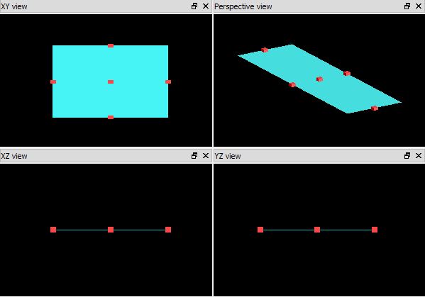
 This is a true 2D rectangle (or a surface object), which has no thickness in the normal direction. This object can be used with the graphene model using the surface conductivity approach.
Geometry tab
- Surface normal: X, Y or Z. This is the surface normal of the 2D rectangle. When a direction of the normal is selected, the 2D rectangle object will be rotated accordingly and the corresponding direction options to specify span and min/max values will be grayed out. The 2D rectangle object has no thickness.
- X, Y, Z: The center position of the object
- X MIN, X MAX: X min, X max position
- Y MIN, Y MAX: Y min, Y max position
- Z MIN, Z MAX: Z min, Z max position
- X SPAN, Y SPAN, Z SPAN: X, Y, Z span of the object
Material tab
The material options are as follows:
- MATERIAL: The material assigned to a 2D rectangle is filtered. It can only be a dielectric with fixed index or a graphene material type.
- OVERRIDE MESH ORDER FROM MATERIAL DATABASE: Select to override the mesh order from the material database and manually set a mesh order. The mesh order is used by the simulation engine to select which material to use when two materials overlap. See the mesh order (optical) or mesh order (electrical) section for more details.
- MESH ORDER: Set the mesh order in this field if the OVERRIDE MESH ORDER FROM MATERIAL DATABASE option is selected. If the option is not selected, the field displays the material's default mesh order from the database. For example, a material of mesh order 1 will take precedence over a material of mesh order 2.
[[Note:]]Mesh order between 2D and 3D objects
- 2d objects always take priority over 3d objects. For example, a 3d cylinder overlapping a 2d rectangle will not create a hole in the 2d rectangle, regardless of their mesh order.
- 2d objects respect mesh order among themselves. For example, a 2d rectangle with RLC overlapping a 2d polygon with PEC. The material of the overlap is determined according to mesh orders.
- Please refer to the Understanding mesh order for overlapping objects for further information.
INDEX: The refractive index of the structure, when the material type is <Object defined dielectric>. The index must be greater than one.If <Object defined dielectric> is selected, then the INDEX property must be set.
- Anisotropic index: To specify the anisotropy, use the "Surface normal" option in the geometry tab.
- Spatially varying index: This is not supported in this 2D rectangle object.
- INDEX UNITS: Only relevant when specifying a spatially varying equation in the INDEX properly described above. Specify the units (nm, um, m) of the x,y,z position variables.
- GRID ATTRIBUTE NAME: Enter the name of the grid attribute that applies to this object, see the grid attribute section
Rotations tab
Rotate objects by setting the following variables:
- FIRST, SECOND, THIRD AXES: Select rotation axis. Up to three different rotations can be applied.
- ROTATION 1,2,3: The rotation of the object in a clockwise direction about each axis, measured in degrees.
|
Note: Axis rotation This object does not support arbitrary angle of rotation on the non-normal axis. For example, with z axis being the normal, rotation of 30 degrees along z is allowed. However, rotation of 30 degrees along x or y axis is not allowed. Also note, the "Surface normal" option in the "Geometry tab" also rotates the object accordingly. |
Graphical Rendering tab
The graphical rendering tab is used to change how objects are drawn in the layout editor. The options are:
- RENDER TYPE: The options for drawing the objects are detailed or wireframe. Detailed objects are shaded and their transparency can be set using OVERRIDE COLOR OPACITY FROM MATERIAL DATABASE.
- DETAIL: This is a slider which takes values between 0 and 1. By default it is set to 0.5. Higher detail shows more detail, but increases the time required to draw objects. This setting has no effect on the simulation.
- OVERRIDE COLOR OPACITY FROM MATERIAL DATABASE: When unselected the opacity is determined from the material database. When selected, you can specify a value for ALPHA between 0 (transparent) and 1 (opaque) for the object, depending on how transparent you want the object to be.
See also
Structures, Structures - 2D Polygon, Material conductivity models, Creating 2D conductivity from permittivity data, Graphene, add2drect