Stray light analysis of an optical system and the associated image quality assessment require consideration of both lens geometries and the optomechanical components that constrain them. Stray light can originate from several sources, including specular reflections, scattering, edge diffraction, and interactions with the optomechanical elements in the system. Because of this variety, the analysis involves identifying all the potential stray light contributors in an optical system and minimizing (or ideally eliminating) their impact on the system’s performance.
Simulation is key to conducting robust stray light analysis. However, correctly setting up the model and tracing the root causes of stray light issues are often challenging tasks.
Automation is therefore key to improving repeatability, reducing user‑induced errors, and accelerating iterative stray light investigations.
This article provides optical and stray light engineers with three custom Speos/SpaceClaim scripts designed to automate critical steps in the Stray Light Analysis workflow.
To get the most out of these scripts, you should be familiar with:
- Ansys Speos & SpaceClaim 25R2 or later versions (CAD-integrated interface).
- Physical Camera simulations
- Optical Design Exchange
These scripts are designed to be integrated directly into the SpaceClaim–Speos interface, improving accessibility, and reducing manual setup time.
The three scripts address the following tasks:
- Parametric Surface Source Setup Script
- Physical Camera Setup Script
- Speos Lens Ghost Extractor Script
Important notice: The scripts listed are available in the attachments of this article. All of them are included in separate folders with their corresponding names and are provided under the MIT License, included also in the attachments.
How to integrate SpaceClaim scripts in Speos
SpaceClaim scripts (*.scscript) can be stored in a specific folder and are made directly accessible via the Ansys Speos User Interface.
To do so, it is only necessary to extract the *.scscript files in the attachments from their correspondent folders and place them in the following root directory: %appdata%\SpaceClaim\Published Scripts (or search directly for C:\Users\username\AppData\Roaming\SpaceClaim\Published Scripts). After this step, it is necessary to restart Speos.
Then, the script icon will automatically appear in Speos interface, accessible via Tools tab > Scripts, under the name of the stored script.
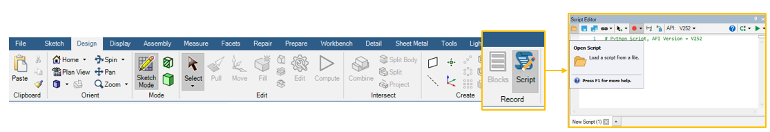
If manual execution of the script is preferred, the script must be open through the SpaceClaim Script editor, which can be found in Design tab > Record > Script.
Script execution - Best practices
To ensure the proper execution of SpaceClaim scripts and to minimize errors, we highly recommend following these best practices:
- It is not recommended to have more than one Speos project open when executing a script.
- While the script is being executed, it is highly recommended to follow the step-by-step instructions appearing in the Speos interface.
-
Whenever user input is required, you must validate the selection by clicking the Complete icon (see image below). Please note that the Abort icon does not stop the script; it only cancels the current user‑input selection and applies the default value instead.
User inputs may be requested either in the Options–Selection tab or through selection operations in the Speos interface.
- It is not possible to use other Speos/SpaceClaim features, perform additional actions, or create new components while the script is running.
- To terminate a script while it is running, you must press the ESC key.
Automated Parametric Surface Source Setup Script
The purpose of the Automated Surface Source Setup script (AutoParametricSource26R1.1) is to simplify the setup of sun (and surface) sources in Speos, saving time, and reducing the risk of manual errors during the workflow.
Prerequisites
- A reference coordinate system for the parametric source generation.
Description
The script performs the following actions, where the user can introduce personalized input values to adapt source generation to their own use case (default input values are given by default):
-
The user is asked to select a reference coordinate system for the sun source generation. The orientation of this axis system must be the following to ensure that the parametric sources are correctly generated: Z axis must correspond to the optical axis of the system, with its positive axis parallel to light propagation direction. Along with X and Y axis, azimuth and elevation angles will be defining each source position in reference to the optical system (see image below).
-
The user can then select between two setup modes: sun source defined model or custom surface source model.
If the sun source option is selected, the user will have the option to specify the target illumination area diameter, defined as the desired total illuminated area that will determine the source size. The target irradiance value on the target area is also a user-defined parameter, along with the desired minimum and maximum azimuth and elevation angles (with its corresponding step angles). After that, parametric surface sources with sun source values will be generated.On the other hand, if custom surface source is selected, the user will be asked to introduce some additional input value in addition to the first option:
- Aiming area diameter and target average irradiance value in this area (see image below).
- Intensity distribution angle for the surface source.
-
Spectrum type: monochromatic (if selected, the wavelength value will be asked), black body (temperature in Kelvin needed as input) or library (the user has the option to load its own *.spectrum file by typing in the Options-Selection the name of the file).
- With the previous input values correctly defined, the user will have the option to select between four different scanning methods to generate the parametric surface sources. Depending on the method, some extra parameters may be needed:
- Horizontal scan (elevation angle = 0 deg): surface sources will be only generated along the horizontal axis (y = 0). The user will be asked to introduce the starting and end angle for the azimuth angle, and the step (in deg) between each generated source.
- Vertical scan (azimuth angle = 0): surface sources will only be generated along the vertical axis (x=0). The user will be asked to introduce the starting and end angle for the elevation angle, and the step (in deg) between each generated source.
- Scan along the sensor diagonal: in this method, sources are generated along the sensor’s diagonal. Therefore, the requested inputs will be sensor’s dimensions, starting and end scanning angles, and the corresponding step. Azimuth and elevation angles are calculated taking these inputs into account.
-
Custom position: the user will introduce starting and ending values (and corresponding step) both for azimuth and elevation angles.
-
All the generated surface sources can be found in the simulation tree under a component named Parametric source surfaces.
Note: The end scan angle must not be set to zero. It is recommended to use a value of at least 0.1° for these types of cases.
Automated Physical Camera Setup
The script AutoPhysCam25R2 simplifies the setup and use of the Physical Camera Sensor with its associated simulations, enhancing the overall user experience, saving time and reducing risk of manual errors during the workflow.
Prerequisites
- Optical Design Exchange component. Please note that Optical Design Exchange component must be the same version as the Speos one to be compatible.
- CAD component with optomechanical geometries.
- Source component to be included in simulation (Optional).
Description
The script performs the following actions, which are separated into two main blocks:
-
Automated setup: Fully automates the positioning and configuration of the Physical Camera Sensor based on the user’s selection of the .odx file, optomechanical geometry, and selected front optical face, taken as reference for the Physical Camera sensor creation.
The script will generate a Speos Lightbox containing the .odx and optomechanical geometries with its material properties. This Speos Lightbox can be black boxed, encrypted, and shared with camera integrators using Speos with the Physical camera sensor ensuring lens manufacture's IP is protected.
Once the Physical Camera sensor has been created, the user can choose if they would like to continue with the simulation set-up. If so, script will run step 2, Simulation Execution. -
Simulation execution: Runs a direct or inverse simulation with the Physical Camera Sensor in two steps:
- The first simulation, “Physcam_no_seq”, generates the sequence file (required to be run on CPU per version 2025R2 and older).
- The second simulation, “Physcam_seq”, uses the sequence file generated from the first step, and the data from the first N sequences to execute and generate the results (compatible with CPU and GPU).
During this second step, the user will be asked to select the source to be included in the simulation and the number of rays to be computed for both simulations.
Tip: You can modify the script to run the second simulation on GPU (if available).
Note: Please note that, for physical camera sensor definition, Optical Design Exchange default local meshing values have been modified. However, we highly recommend reviewing these parameters and modifying them according to the use case needs.
In the attachments for this article, you will find a video explaining the Automated Physical Camera script step by step using the Speos data available in Stray Light Analysis – Smartphone Camera – Ansys Optics.
Speos LensGhostExtractor25R2 Script

Prerequisites
- A simulation using the Physical camera sensor.
Note: only Speos 2024R1 (beta) and later versions (2025R1, official release) support Physical Camera Sensor.
Description
In the first stage, the script analyzes an .OptSequence file generated by the Physical Camera Sensor by identifying ray‑path sequences that include a user‑defined number of consecutive specular reflections within the same lens element. This phenomenon is a common indicator of high-energy internal lens ghosts produced by total internal reflection (TIR).
The script extracts the relevant sequences and generates a summary report that details all detected ghost‑path sequences sorted by their energy. It also produces a new, filtered .OptSequence file containing only the identified ghost sequences.
Visualization of Ghost-Reflection Sequences
In the second stage, the filtered .OptSequence file can be used with the Physical Camera Sensor on GPU to visualize only the problematic ghost paths. This enables focused analysis and high‑quality, converged simulation results of internal lens‑ghost reflections.
Additional resources
Stray Light Analysis Overview – Ansys Optics