In this example, we introduce a simulation workflow to analyze and optimize the optical performance of a smart speaker’s lighting system under specific lighting conditions. The lighting system is designed using Ansys Speos software, embedded inside Ansys SpaceClaim. An optimization of the system is done using the integrated Ansys Speos Optimization tool.
Authored By Mina Nazari
Software Prerequisites
To be able to use this example, the following products and solutions need to be installed on your computer:
- Ansys Speos 2025 R1 or later
Overview
Understand the simulation workflow and key results
The perceived quality of lighting systems carries substantial importance across various industries, especially in the High Tech, Lighting, and Automotive sectors. In these fields, the precision of measurements, the accuracy of color representation, and the achievement of optimal visual performance are critical factors. These elements not only enhance the functionality of the systems but also contribute significantly to the overall user experience. Ansys Speos software, powered by state-of-the-art Non sequential ray-tracing technology offers an array of advanced features to design, analyze and validate lighting systems. It streamlines lighting design processes with optical part design features, ensures compliance with regulations, and provides realistic human vision rendering in diverse environments. Additionally, it offers the capability to generate dynamic lighting animations that provide functionality to simulate the lighting system within a 3D environment, dynamically. With this solution, users can optimize the components and construct an accurate perception of the 3D scene with lifelike illumination and perform physically unbiased photometric/radiometric rendering.
This application example focuses on the capabilities of Ansys Speos for optimizing the lighting system and validating the performance and is modeled by assuming that a CAD model for the Smart speaker system is already available.
Step 1: Design Optimization :
O ptimization of lightguide system using Ansys Speos Built-in optimizer.
Step 2 : Colorimetric Evaluation of Lighting Systems, using Virtual Lighting Controller:
Use Virtual Lighting Controller to fine-tune LED power settings to fulfill specific color requirements without the need for further simulation.
Step3: Virtual Animation :
The Virtual Lighting Animation Tool enables users to define timelines and control the power ratios of individual LEDs or sources.
Step 4: Evaluate Glare:
The Human Vision Lab within Ansys Speos enables calculation of luminance and color interpretation perceived by Human Vision.
Run and Results
Instructions for running the model and discussion of key results
To explore the smart speaker lighting performance, we optimized and validated the system performance in 3D scene.
Step 1: Design Optimization
The Ansys Speos Optimization feature helps you get the best of your optical system by finding the ideal variable values according to the target values of interest. This tool offers diverse optimization modes, variable types, and target measurement capabilities which is listed below:
Optimization Modes:
- Random Search Algorithm: Explores solutions randomly, useful for initial exploration in complex scenarios.
- Design of Experiment (DoE): Allows definition of variable values, beneficial for systematic parameter study.
- Plugin Integration: Enables integration of custom optimization algorithms for tailored analysis.
Variable Types:
- Simulation Variables: Derived from light simulation parameters in Ansys Speos.
- Design Variables: Stem from features in Ansys Speos optical part design.
- Document Variables: Generated from scripts and CAD models in Ansys Speos.
Targets:
- Measurable factors linked to specific simulation results, to be used as Merit function to optimize
In this example, we use a smart speaker model to demonstrate Ansys Speos' built-in optimization capability for refining the design variables. The Smart speaker, as shown above, consists of a limited number of LEDs positioned above a lighting ring. This ring guides the light through the diffuser and ultimately out of the device. In this example, the lighting ring has a white reflective optical property, with added patterns of same material property to reduce intensity variations. To achieve light uniformity around the ring, two design variables across the ring are optimized (orange): the top radius of curvature at both the internal (blue) and external (green) light patterns within the light ring.
To generate the irradiance result of the initial system prior to optimization, we started by conducting a “Direct simulation”, called 'Lit'. Within the Lit simulation irradiance results, we measured the RMS contrast on 7 points using the measure tool in the Virtual Photometric Lab. Subsequently, we exported the measurement as a template and integrated this template into our irradiance sensor setup, establishing a measurable factor directly linked to the simulation outcomes. This factor served as the Merit function for our optimization purposes.
To proceed with optimization:
- Launch Ansys Speos 2025 R1 and open the file named 'Smartspeaker_Optimization.scdocx' from the downloaded folder.
- Navigate to the Light Simulation tab and select Optimization .
- In the 3D view, choose the Lit simulation that you want to optimize.
- Within the optimization definition section, from the Mode drop-down list, select the Random Search optimization mode and define the Stop condition as shown below:
- To add variables, select Document variables tab
- Click the plus icon, to open the Document variables list and select the following parameters to vary.
To set optimization targets that match our desired outcomes and assess the effects of variables, we use a predetermined set of metrics. For instance, as mentioned before, we export the RMS contrast measure at multiple points along the polyline in the irradiance result. With the corresponding *.xml template assigned to the irradiance sensor we can define the RMS contrast as a target for optimization purpose.
- Within the Optimization definition, navigate to the Variables panel and select the Targets tab. Click on the plus icon to open the Document variables list.
- Check the RMS_constast measure to publish it as a target and Close the Targets list.
- In the Targets tab, you can set the Target value to reach (Merit function minimize) or from which to move away (Merit function maximize) and its Weight. In this example, set up the following:
- In the Simulation tree, right-click the optimization feature and select Compute or GPU Compute to run the optimization on GPU if you have Nvidia Graphics card on your computer. If you don't have one, select 'Compute' to run your simulation using the CPU.
- After the optimization process concludes, Ansys Speos will generate an HTML report. You'll be prompted whether to replace the initial variable values with the optimal solution found. Click ' Yes ' to proceed with the replacement. You can check the new variable values in the Group tab.
- In the Simulation tree, right-click the Light_Sim Simulation and select Compute or GPU Compute to generate radiance results from 30 degree and irradiance results from top view. In the Light_Sim Simulation explore the optimized irradiance results.
As shown above, the RMS contrast has improved, decreasing from ~0.1 to ~0.04, enhancing the light uniformity extracted from the smart speaker diffuser. This is achieved through optimization of design parameters, the radius of curvature at both the internal and external light patterns within the light ring.
Step 2: Colorimetric Evaluation of Lighting Systems: using Virtual Lighting Controller
In Ansys Speos, you can assess the colorimetric aspects of your design by examining different Photometric maps, such as illuminance, intensity, and luminance. You can check chromaticity coordinates for each pixel or measurement area to ensure compliance with regulations.
In this example, we ensure color matching with standards by adjusting light sources power through the Virtual Lighting Controller tool in Ansys Speos. This Tool allows for fine-tuning layer contributions, like sources, as a post processing step without the need of rerunning simulations.
- From the Simulation tree, double-click on the 'Light_Sim.Radiance 30deg.xmp' result within Light_sim simulation that you computed in Step 1, to open the radiance map in the Virtual Photometric Lab and assess the light distribution.
- For colorimetric analysis, use the Chromatic data tool within your results. Note in Speos it is recommended to use the Photometric Lab and not the Human Vision Lab for colorimetry analysis.
- The current color data is displayed at the cursor's location on the diffuser area in the xmp map. Select xyY in colorimetric space type.
- To facilitate color comparison, activate the Reference color checkbox to establish a reference color of 0.33 / 0.33 / 100. Set DeltaE xyY for calculating DeltaE values between the reference color and the selected color.
Within the colorimetric diagram, you have the option to access a menu where you can choose to display various information, such as Colorimetric Standards. This allows you to define or add your own standards for exploring whether optical design meets specific requirements. You can download some standards from the Ansys Material Library.
- Right-click on the colorimetric diagram and select a .cls file from the Standards option. For instance, you can choose SAE J578 from the Automotive menu. Then, examine the colorimetric data on smart speaker diffuser region to verify if the color within that area falls within the specified white standard area.
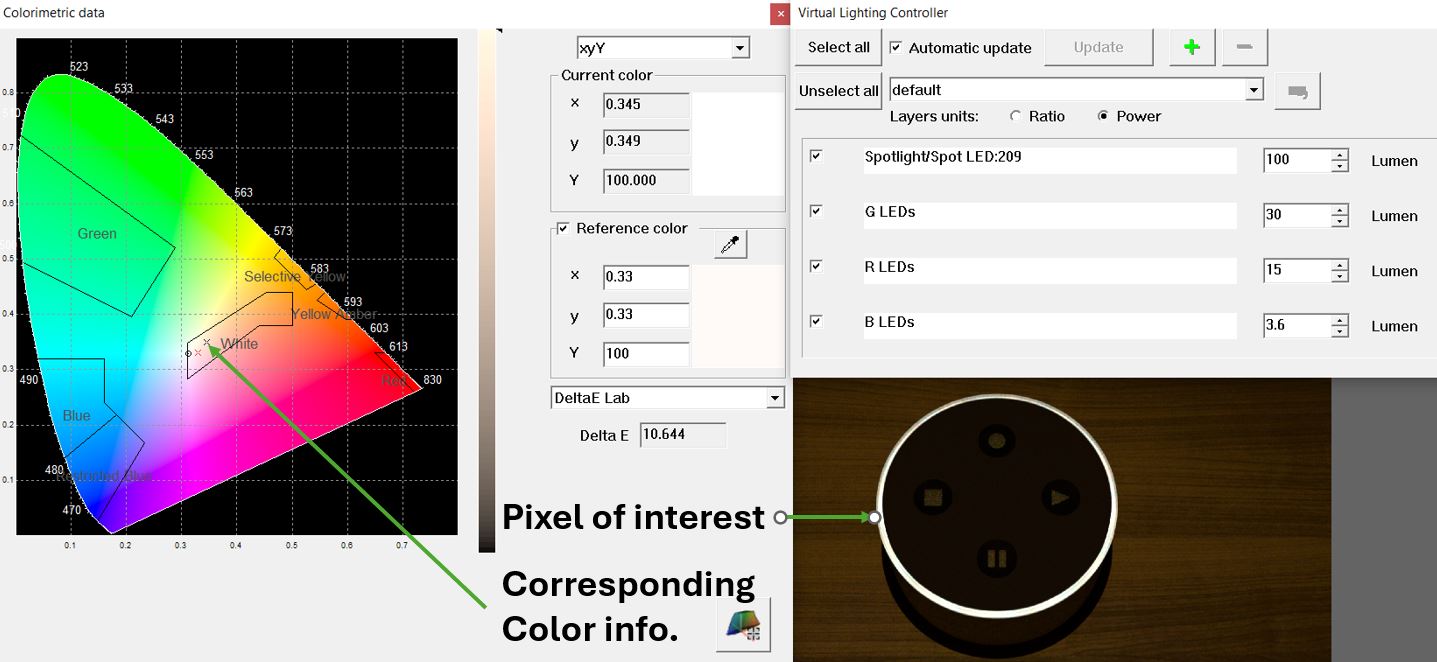
- As the light emitted by the smart speaker isn't in the Standards white area, we need to fine-tune the contribution of LEDs of different colors to meet the standard. To achieve this, we're utilizing the “Virtual Lighting Controller” tool, enabling us to adjust source contributions without the need for running new simulations.
- Access the Virtual Lighting Controller icon from your *.xmp results. Adjust the power of layer units until the color of your Region of Interest (ROI) aligns with the standard area.
- Once adjusted, save the result.
Step 3: Virtual Animation
The Virtual Lighting Animation tool allows you to create animations that visualize power variations across different light sources. This can be achieved due to Ansys Speos capability of layering results based on source power. By defining timelines for each layer of a loaded XMP result, you can generate dynamic videos. This Virtual Lighting Animation tool is accessible through both the Virtual Photometric Lab and the Virtual Human Vision Lab.
- In the Simulation tree, right-click the Light_Sim.Animation simulation and select Compute or GPU Compute to generate radiance results from 60 degree.
- Double-click on the 'Light_Sim.Animation.Radiance 60deg.xmp' result within Light_Sim.Animation simulation to open the radiance map.
- To generate a video showing the animation of LED functions in this smart speaker, Open Virtual Lighting Animation from Tools tab.
- In the Virtual lighting animation window, from file menu select open and browse for the Light_Sim.Radiance 60deg.xmp map in “Speos output file” folder and open it.
- In the Virtual lighting animation window, from file menu select Import and browse for the already created animation template “SS-Anime.csv” file from “Speos output files” folder.
- In the Virtual Lighting Animation tool click on Edit tab and select Preferences . A preferences windows opens, in which you can set the preference for creating the animation such as using photometric or human vision lab data. In this case, we select the virtual photometric lab, set the maximum value to 11000 and Animation parameters to 5 frame per second (FPS) and apply.
- In the Virtual Lighting Animation tool click on Operation tab and select Generate animation. An *.avi video file is created in the same folder as the XMP file.
Step 4: Evaluate Glare
The human eye possesses a great dynamic range, capable of detecting luminance levels spanning from 1E-6 cd/m² to 1E8 cd/m². For example, typical monitors have a dynamic range lower than 1E3 cd/m². The Virtual Human Vision Lab addresses this limitation by restoring contrasts as perceived by observers, compensating for display limitations, and considering human eye behavior for accurate simulations. Using the Human Vision Lab, you can examine the final image that ensures precision and incorporates effects like glare when the eye receives light from optical systems, as illustrated bellow
- Open the Light_Sim.Radiance 60deg.XMP result from the Light_sim_Anime simulation. Use the file menu to select ' Open with Virtual Human Vision Lab ' to view the results in the Human Vision Lab.
- Then, from the top menu select Glare effect.
To explore additional vision parameters, select Vision parameter from Tool menu and analyze how conditions of observation, observer and simulation parameters impact the results.
As shown in this example, Ansys Speos solution, utilizing advanced ray-tracing optical simulation technology, provides a comprehensive platform for designing, analyzing, and validating lighting systems. It facilitates streamlined design processes, and validation and realistic human vision rendering in different lighting scenarios and generation of dynamic lighting animations within a 3D CAD environment. The process involves design optimization using Ansys Speos' built-in optimizer, colorimetric evaluation by adjusting the light as a post processing using the virtual lighting controller, virtual animation with the Virtual Lighting Animation Tool, and glare evaluation utilizing the Human Vision Lab within Ansys Speos.
Important Model Settings
Description of important objects and settings used in this model
As described in the step-by-step workflow above, the virtual lighting animation tool enables you to generate the animation as a video file according to the settings you defined. The Virtual Lighting Animation tool can be accessed from Virtual Photometric Lab or Virtual Human Vision Lab. For generating an animation, the following files are needed:
- The XMP map includes one or multiple sources
- A specific timeline for each source (The timeline can be defined using an animation template (*.csv file).
In the corresponding *.csv file, the time frames are represented in the Time column and the power ratio of all sources of the XMP are represented in other columns as function of the time frame while a linear interpolation is applied between each point of the timeline.
User can iterate on the timeline (timeline event or animation template), modify the timeline, regenerate the animation and then export the project as *.xml file.
Taking the Model Further
Information and tips for users that want to further customize the model
Expand your simulations to include various lighting scenarios, encompassing both LED lights, room lighting and ambient lighting, such as the Studio Light as specified in our sources in your simulation.
Additional Resources
Additional documentation, examples and training material