In this example, we will model a simple uniaxial LCD layer. For more complex LC orientations, see Twisted Nematic LCD.
Simulation setup
The anisotropy resulting from the orientation of liquid crystals cause light polarized along the LC director to propagate at a different velocity than light polarized along the perpendicular direction. This birefringence leads to a change in polarization between the incident light and the light that is transmitted through the LC layer.
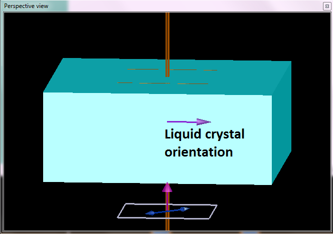
To model this effect in FDTD, we will use an anisotropic material and a LC grid attribute object, which allows us to specify an arbitrary orientation for the LC layer. All we have to do in this case is to set the angles “theta” and “phi” in the LC attribute object corresponding to the desired LC orientation. In LCD.fsp, we start with a plane wave polarized at 45 degrees in the x-y plane, and use the polarization ellipse analysis group to study the change in polarization for the transmitted light. The polarization ellipse analysis object can be found in the object library, ![]() , in the far field projections section.
, in the far field projections section.
Results
We will look at the results for two types of LC orientation: the first with the LC director pointing along the z axis (theta = 0, phi = 0), and the second with the director pointing along the y axis (theta = 90°, pi = 0). In the first case, the light polarized along the x and y directions will still propagate at the same velocity, so we do not see any change in the polarization of the output light. In the second case, the light polarized in the y direction will propagate at a different velocity than x, and we will see a change in the polarization as a result of the difference in phase between the two components. This phase difference is directly proportional to the thickness of the LC layer:
$$\Delta \phi=\frac{2 \pi h \Delta n}{\lambda}$$
To determine the optimal thickness required to change the polarization by 90 degrees (ie. from 45 degrees to -45 degrees), we set up a parameter sweep project to sweep the thickness of the LCD layer from 2 to 3 microns, and track the ellipticity (ie. the ratio between the major and minor axis) as a function of this change. The result of the parameter sweep is shown below (you can see this by right-clicking on the sweep project, and selecting Visualize-ratio) .We can see that the optimal thickness is around 2.75um.
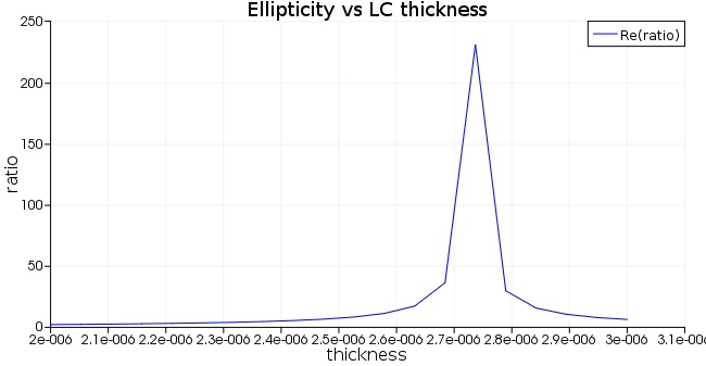
This is the expected result for \(\Delta \phi=\pi\), since \(h=\frac{\lambda}{2 \Delta n}=2.75 \mu m\) .
See also
LC rotation object, Twisted Nematic LCD, Tuning of SOI ring resonator, Optical switch, Optical phased array