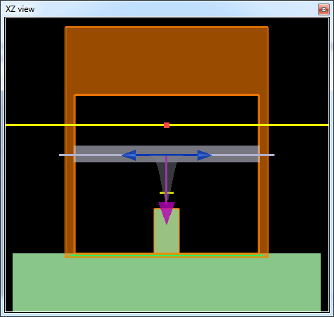
In this example, we construct a complete three-dimensional model of the interaction of a focused optical beam and the structured, gold surface of a typical DVD disc. The goal is to determine the minimum feature size of the gold post that results in a strong modulated signal, such that maximum information can be stored on the surface of the DVD.
To reproduce the following results, open the simulation file, then run the attached script file. The script runs two simulations with and without the metallic bump.
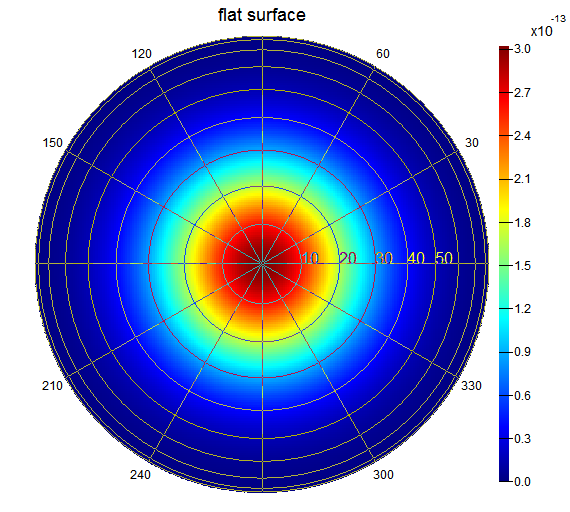
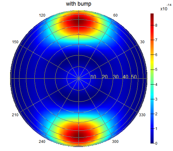
First, we calculate and plot the near field with and without the metallic bump.
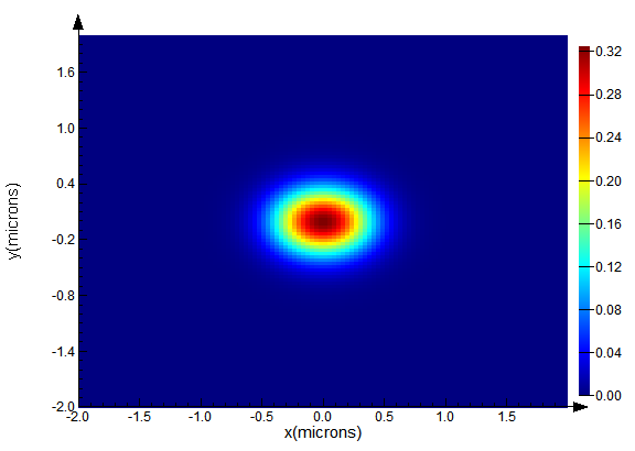
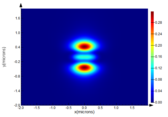
Without the gold post present (left above), the reflected beam looks almost identical to the incident beam. Once the post moves under the beam (right above), the reflected beam contains a lot of structure. From the near-field profile plotted, we can see that only the central part of the beam interacts with the gold post strongly.
Next, we look at the far field radiation pattern for the same two simulations.
Without the bump, the majority of the reflected power is would be collected with an objective with the same divergence angle as the Gaussian source. With the metal post present, there is significant scattered field in the y direction, greatly reducing the amount of power that would be collected by the objective.
To quantify this, we use the "signal" analysis group, which returns the result "signal" calculated from integrating the far field results over the cone corresponding to the specified divergence angle. Note that the setup script in the "model" element automatically reads the divergence angle of the Gaussian source and sets the divergence angle of the analysis group to the same value. The script in the "analysis" tab of the analysis group (shown below) then calculates the portion of the reflected power withing the defined divergence angle.
e2 = farfield3d("reflection",1,200,200,1,1,1,1);
ux = farfieldux("reflection",1,200,200,1);
uy = farfielduy("reflection",1,200,200,1);
# calcualtes portion of e field within the divergence angle of the lens (or the Gaussian source)
signal=farfield3dintegrate(e2,ux,uy,divergence_angle)/farfield3dintegrate(e2,ux,uy);
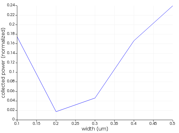
Finally, we can set up a parameter sweep that varies the dimension of the metallic bump in order to determine when the minimum signal is returned. We calculate the signal as a function of the post width for a fixed post length (click on the sweep project and select Visualize -> signal to plot the following result in the Visualizer).