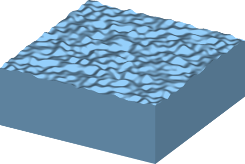
In this example, we will consider a surface with a nanoscale structure. The surface can be characterized using a Bidirectional Scattering Distribution Function (BSDF). This function relates the intensity of an incoming ray to an outgoing ray for all angles of incidence and reflection/transmission.
BRDF and BTDF
Generally, we can split the problem into one of calculating the Bidirectional Reflectance Distribution Function (BRDF) to characterize the reflection of the surface and the Bidirectional Transmittance Distribution Function (BTDF) to characterize the transmission of the surface. In addition, for this example, we will consider that the structure has azimuthal symmetry and therefore the BSDF does not depend on the incident azimuthal angle.

For many surfaces, the specular reflection and transmission is much larger than the diffuse scattering. It can be useful to separate these two contributions, as shown in the figure below. In this case, we can treat the BRDF and BTDF as a relatively smooth function for many surfaces, which makes interpolation near the specular directions much easier.

Simulation methods
There are two approaches that can be used for calculating the BSDF, the Gaussian beam, and the plane wave.
|
Gaussian beam with PML boundaries on all sides. |
Plane-wave with Bloch boundary conditions on the x and y boundaries. |
|
|
|


The Gaussian beam approach uses a finite-size gaussian beam as the incident field with PML boundaries on all sides. The disadvantage of this approach is that the diffraction of the Gaussian beam will always be included in the calculation of the BSDF. This means that the BSDF cannot be accurately determined near the specular directions because we see the diffraction of the finite-size gaussian beam which generally dominates non-specular scattering from the surface. However, for surfaces that lead to very diffused light, it can be a good method.
The plane wave uses Bloch-periodic boundary conditions. This means that the structure is treated as a periodic repetition of the surface. The angular distribution of reflection and transmission is only calculated for directions corresponding to the grating orders of the periodic structure. As long as the period is large enough, this provides enough angular resolution. The rough surface structure from the object library will create a periodic structure with no discontinuities when periodic boundary conditions are used. The advantage of this method is that there is no inherent diffraction of the source beam. For example, a completely flat surface will show that light is purely scattered specularly, whereas the gaussian beam method will show that the beam spreads due to diffraction of the beam. In addition, the plane wave method allows the specular intensity to be perfectly separated from the non-specular scattering, which can be useful if some smoothing of the non-specular scattering is required. The disadvantage of this method is that the number of scattered orders depends on the angle of the incident beam, which makes data processing somewhat more complicated. Furthermore, the number of layers of PML absorbing boundaries generally needs to be increased to account for the poor performance of PML at steep angles of incidence.
In the remainder of this application example, we will use the plane wave method.
BRDF Theory
In this example, we will consider a weakly scattering, thin grating (rough surface with periodicity) at normal incidence and compare the calculated BRDF with the theoretical result using the Born approximation. We will study this surface using the plane wave method.
Generating a rough surface with a correlation length
The [[bsdf_simple.fsp]] file has a structure with a rough surface that is generated to have a specified sigma RMS (σ) and correlation length (Lc). In this example, these quantities are related to the correlation function by
$$\langle H(\vec{r}) H(\vec{r}+\vec{\delta})\rangle=\sigma^{2} \exp \left(-\left(\frac{\delta}{L_{c}}\right)^{2}\right)$$
where the average is carried out over all positions on the surface, r, and H is the surface height defined such that
The rough surface structure can optionally generate some figures as shown below. To produce these plots, right-click the 'rough_surface' structure group and enter '1' in the 'make plots' parameter, and then click 'ok.' When a warning message pops up, reading "This requires a czt of a 2d matrices of size 401x401! Do you want to proceed?", click 'Yes.'
For this simple case, we will run a single simulation at normal incidence.
 |
 |
| Rough surface in k-space | Rough surface in real space |
 |
 |
| Correlation function calculated numerically compared with theory | Correlation function calculated numerically compared with theory (zoomed in) |
Analysis of results
The script file bsdf_simple.lsf can be used to perform the analysis. It first calculates the angular distribution of scattered orders, which is shown on a log scale below. Note the resemblance to the original random surface in k space.

It then uses the script function farfield3dintegrate to integrate over a series of collection angles, with an integration area corresponding to a cone with a 5-degree half-angle. We average over 50 azimuthal angles. We then can compare to the theoretical result for angles away from normal incidence.


The agreement between theory and simulation is very good above 10 degrees. The agreement below 10 degrees is not so good because the results come from only a few data points. To improve this agreement, we would need to simulate a beam that is incident on several different regions of the surface and average the results. This will be done in the following section.
BSDF Calculation
We now want to generate the BRDF and BTDF for a particular surface. In this example, we will use the same surface from BRDF theory to generate a BRDF and BTDF but any surface could be used. In this study, we will use the plane wave method.
Simulation
The starting fsp file is bsdf_simple.fsp. The script file bsdf_calculation_bloch.lsf will calculate the BRDF and BTDF for 5 different incident polar angles. We assume that the surface roughness has azimuthal symmetry, and we can rotate the structure by 90 degrees. In addition, we average over 9 random surfaces generated with the same settings. This is similar to averaging over 9 different locations on the surface in an experiment. To obtain unpolarized results, we will average the response of S and P polarization on the input. The total number of simulations is therefore 5 x 2 x 9 x 2 = 180. The user can choose to rerun the simulations, or simply rerun the analysis when running the script file.
Analysis
For each angle of incidence, we calculate the angular distribution of reflected and transmitted orders. In this example, there are approximately 50x50 orders, although the number in transmission is different than the number in reflection due to the different refractive index. This number can be increased by increasing the area of the simulation.
We can then separate the specular transmission and reflection by identifying the 0th order in each case. We assume that the specular is much stronger than the other orders and that is indeed the case. To separate the specular light from the diffused light, we assume that the diffused light in the specular direction is the average of the light diffused to the (+1,0),(0,+1),(-1,0), and (0,-1) orders. To conserve energy, we also subtract this small amount from the specular power already identified. This separation at precisely the specular angle is somewhat arbitrary but provides a smooth function for the diffuse component of the BSDF. We can then calculate the BRDF and BTDF by integrating the diffused light over various output angles. In this study, we assume that we can integrate over a 5-degree half-angle cone, and this helps provide some additional smoothing of the results in addition to the smoothing that occurs from averaging the different incident positions and incident azimuthal angles. The user can also specify the half-angle size of the integration region, to modify it as desired.
|
Note : When using the farfield3dintegrate function, we need to multiply by a factor of cos(theta_out). This is because our angular distribution represents the relative power carried in each diffracted order, and not the time-averaged Poynting vector. The user can choose which range of input angles (theta), and output angles (theta_out, phi_out) to calculate. Note that phi_out represents the difference in input azimuthal angle and output azimuthal angle because we have assumed that the surface has azimuthal symmetry. |
Results
The angular distribution of scattered light is shown below for each of the five angles of incidence.
Reflected fields


Transmitted fields


Extracted BRDF and BTDF
In this example, the BRDF and BTDF are calculated for an azimuthal angle of 0. The resulting BRDF and BTDF functions are shown below.


The script also outputs the specular strengths for reflection and transmission, the total reflected and scattered power, and the total power
incident angle, specular R, specular T, total R, total T, total R+T
0, 0.00404571, 0.911121, 0.0257424, 0.974054, 0.999796
15, 0.004939, 0.907587, 0.0257847, 0.973971, 0.999756
30, 0.00841839, 0.893595, 0.0276189, 0.972104, 0.999723
45, 0.0176576, 0.860782, 0.0348971, 0.964782, 0.999679
60, 0.0403746, 0.806879, 0.0528771, 0.944788, 0.997665
Note that the total power is not exactly 1 due to numerical errors. If it is substantially different than 1, it means that there is an error in the simulation setup, or that more layers of PML may be required.
The BRDF, BTDF and specular data is saved to an *.ldf file and can be reloaded as required.
BSDF export to ASAP
We can export the results from the previous section to ASAP *.inr files for use in ASAP simulations. The BRDF and BTDF can be exported with the script file bsdf_export_asap.lsf. This creates 2 *.inr files with the rawdata models. For example, the file brdf_simple.inr or btdf_simple.inr looks like
$CASE LOWER
models
  rawdata

!! begin incidence  0 degrees

    0    0
    -0.996195    0    0
    -0.993136    0    0
    -0.989185    0    0
    -0.984345    0    0
    -0.978622    0    1.08113e-007
    -0.972019    0    9.73739e-008
    -0.964543    0    9.73739e-008
...
!! end incidence 0 degrees
...
!! begin incidence  60 degrees
...

    0.866025    0
    -0.996195    0    3.01866e-008
    -0.993136    0    3.01866e-008
    -0.989185    0    3.01866e-008

!! end incidence 60 degrees

return
$case upper