A grating coupler can be used to launch light efficiently from free space into the waveguide for HAMR application This page explains how to simulate coupling efficiency of a grating coupler using FDTD.
Simulation setup
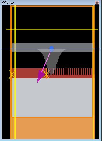
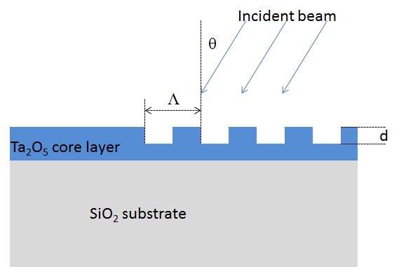
The figure below shows the waveguide structure studied. It consists of a 100-nm thick Ta2O5 core layer on a SiO2 glass substrate and a focused Gaussian beam is incident on structure with an angle θ. To have good light confinement the core layer was chosen to have high index of refraction and cladding layer has low index. The layer thickness of core is designed such that only the fundamental transverse electric mode (TE0) can propagate in the waveguide and the width of the mode field intensity is minimized for excitation wavelength λ = 632 nm. At 632 nm, the refractive index of the core layer is 2.09 and that of the SiO2 layer is 1.47.
In this page, we calculate coupling efficiency as a function of incident angle θ and groove depth d using the parameter sweep capability in FDTD. The coupling efficiency is defined as a ratio between the incident beam power and the guided wave power traveling in the core layer. An analysis group named "efficiency" in the simulation file calculates the coupling efficiency.
Result
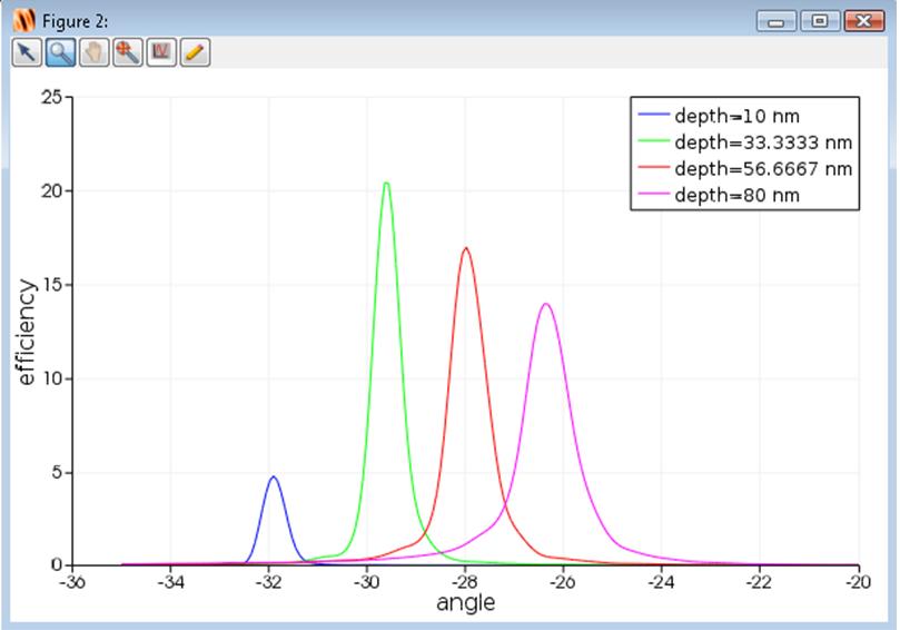
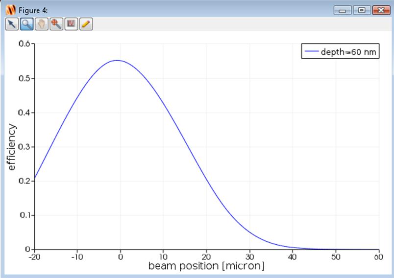
If you run the parameter sweep named "depth" and "beam position" tn the Optimization and Sweeps tab, you can obtain the coupling efficiency as a function of incident angle and beam position as shown below. The figure left below and right show coupling efficiency as a function of incident angle and beam position, respectively.
Related publication
- C. Peng and W. A Challener, "Input-grating couplers for narrow Gaussian beam: influence of groove depth," Optics Express., vol. 12, no. 26, pp. 6481–6490 (2004).
See also
Grating coupler (Photonic integrated circuit example)