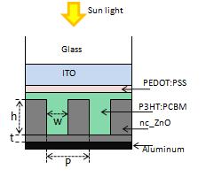
Organic solar cells (OSCs) have various advantages compared with conventional silicon based solar cells; for example, low cost and flexibility. However, it is necessary to improve the low conversion efficiency for many practical applications. There have been a number of recent studies to improve the conversion efficiency by increasing the light absorption with the help of nano-sized structures. One method is to use photonic crystal (PC) structures in the photoactive layer where the light absorption can be enhanced by trapping light as leaky modes within the PC structures. The figure presents an organic solar cell with photonic crystal structure. In this section, we show how to simulate the light absorption within the OSC with PC (PCOSC) using FDTD.
In this example, we consider an OSC in which the bulk heterojenction blend, poly-3-hexylthiophene/[6,6]-phenyl-C61-butyric acid methyl ester (P3HT:PCBM) are used as a photoactive layer. The OSC has a PC structure formed by the bulk heterojunction blend and nc-ZnO as shown in Figs.1 and 2. Due to the existence of waveguide anomalies caused by a resonant interaction of incoming light with a leaky (or a quasi-guided) mode of the PC waveguide, the light absorption can be enhanced compared with conventional flat solar cells.

Fig.2 Screenshot of layout editor of organic solar cell in which 2D photonic crystal with hexagonal lattice is formed
Simulation setup

Fig.3 Screenshot of solar_cell_organic_2D.fsp, 2D hexagonal lattice of photonic crystal are formed in the photoactive layer
Materials
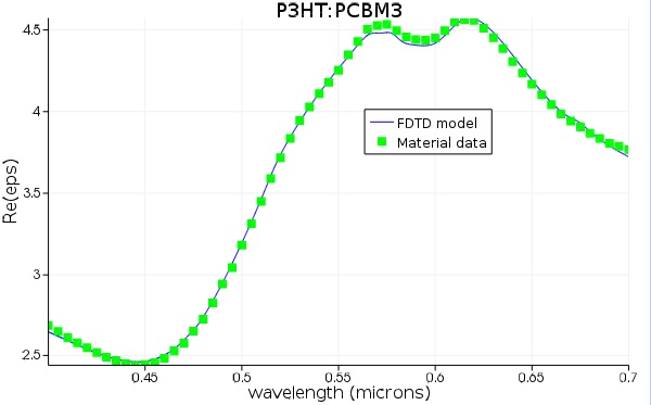
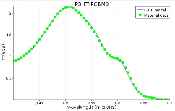
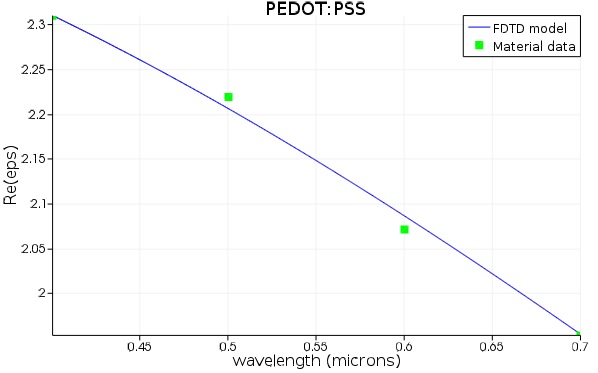
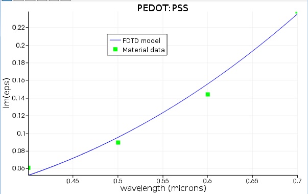
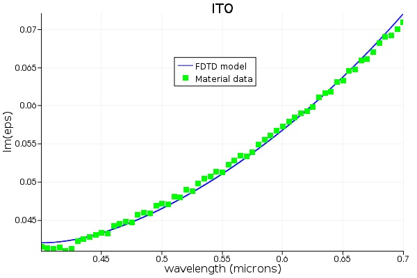
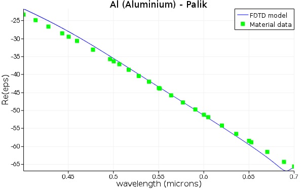
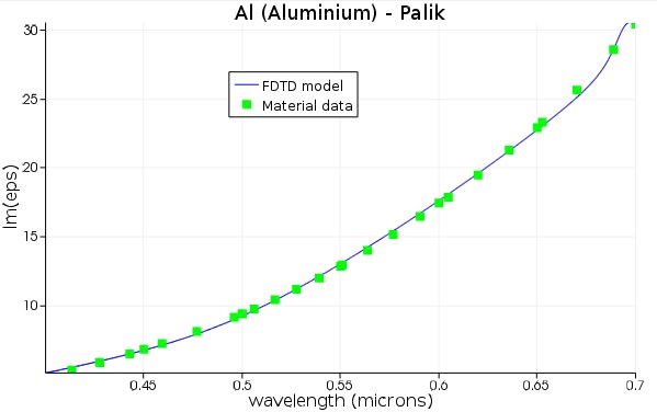
To model the material dispersion of P3TH:PCBM, ITO, PEDOT:PSS and aluminum, the multi-coefficient model (MCMs) is used. This generalized material model provides much better fits to experimental data than conventional models like Drude and/or Lorentz. Fig.2 shows the fitting curves given by the MCMs model for (a) P3HT:PCBM, (b) PEDOT:PSS, (c) ITO, and (d) Aluminum over the solar spectrum range from 400nm to 700nm. The glass and nc-ZnO are considered to be perfectly transparent and their refractive indices are taken as 1.52 and 1.4, respectively. These material data are taken from the literatures listed below:
|
(a) Re(εP3HT:PCBM) |
(a') Im(εP3HT:PCBM) |
|
(b) Re(εPEDOT:PSS) |
(b') Im(εPEDOT:PSS) |
|
(c) Re(εITO) |
(c') Im(εITO) |
|
(d) Re(εAlminum) |
(d') Im(εAlminum) |
|
References for material data
|

Simulation region and sources
The setup for this example follows the guidelines described in simulation methodology. We use mesh accuracy 2 and "conformal variant 0" for mesh refinement at the material interfaces. Since only one unit cell is required for simulation, in the fsp file, only one period is shown. Visualizing the material index using the "index monitor" can make sure that the structure is set up correctly.
We do not directly model the real sunlight spectrum as explained in Methodology. Instead, a normally incident plane wave named "source" with a wavelength range from 400nm to 700nm is used.
Monitors
To calculate the power absorbed in the P3HT:PCBM, two power monitors are used. One, named monitor_3, is located at the boundary between P3HT:PCBM and PEDOT:PSS; and the other, named monitor_4, is located at at the boundary between P3HT:PCBM and nc-ZnO. Using a script function transmission, the absorbed power Pabs (λ) can be easily calculated by
Pabs(l)=-transmission (monitor_3) - ( -transmission (monitor_4))
If we use monitor_1, 2 and 3 with the transmission function, we can also calculate the light absorption in ITO and PEDOT:PSS layer. Furthermore, if you want to calculate the absorption profile, You can use a power monitor and an index monitor named profile and index, respectively, which will need larger memory.
Results
We calculate the light absorption of the PC-OSC and show an absorption enhancement caused by the trapped light as a leaky mode of the PC waveguide structure. We also calculate the light absorption in ITO and PEDOT:PSS layer and show that nearly 20% of the whole absorption in the PSOCS is consumed in these layers. In addition, we calculate the absorption distribution which varies strongly depending on the wavelength. In the following examples, the thickness of the ITO and PEDOT:PSS are fixed to 178nm and 50nm, respectively, and that of P3HT:PCBM is fixed to 193nm.

Fig.5 Light absorption profile within the PCOSC.
In this OSC example, the absorption is mainly in P3HT:PCBM material. In this design, the absorption at longer wavelength can be enhanced by PhC. Here, the period, the diameter and the height of the PC are fixed to P = 460 nm, D = 300 nm and h = 120 nm, respectively and the thickness of the nc-ZnO is set to t=150nm. Users can optimize the design by using the built-in optimization algorithm.
Open and run solar_organic_2D.fsp. Enter the following script in the Script Prompt to plot the absorption:
t3=transmission("monitor_3");
t4=transmission("monitor_4");
f=getdata("monitor_3","f");
plot(c/f*1e6,t4-t3,"Wavelength (um)","Absorption in P3HT:PCBM");
To compare with the case without PhC, switch to the layout mode, disable the "hexagonal lattice" group, and run the simulation again. Then plot the result with these lines:
t3_flat=transmission("monitor_3");
t4_flat=transmission("monitor_4");
plot(c/f*1e6,t4-t3, t4_flat-t3_flat,"Wavelength (um)","Absorption in P3HT:PCBM");
legend("PhC","flat");
The results are shown below:

FIg. 6 Absorption within P3HT:PCBM for 2D PCOSC. Both ITO and PEDOT:PSS are lossy.
As shown above, the absorption at longer wavelength are enhanced, and at around 680nm. Such enhancement may be attributed to the leaky slab mode, which can be investigated by bandstructure analysis.
Related publications
1). John R. Tumbleston et al., "Electrophotonic enhancement of bulk heterojunction organic solar cells through photonic crystal photoactive layer." Appl. Phys. Lett. 94, 043305, 2009. See also http://research.physics.unc.edu/project/rln/.
2). John R. Tumbleston et al., "Absorption and quasiguided mode analysis of organic solar cells with photonic crystal photoactive layers," Optics Express 17, pp. 7670 - 7681, 2009. See also http://research.physics.unc.edu/project/rln/.
3). Doo-Hyun Ko et al., "Photonic Crystal Geometry for Organic Solar Cells," Nano lett. 9, pp. 2742 - 2746, 2009.