Using INTERCONNECT, it is trivial to carry out time domain simulations of externally modulated laser transmitters or direct detection lightwave receivers using different modulation formats. For time domain simulations the user can set the time window and the number of samples, which will define the signal sampling rate used in the simulation. In order to simplify the process of estimating these parameters, one can simply define the transmitter bitrate, the number of samples per bit and the bit sequence length. INTERCONNECT will then calculate the time window, sample rate and the number of samples.
When setting up a simulation system, the sequence length (number of bits) and samples per bit should be large enough to guarantee the accuracy. A longer simulation sequence length may take longer time, hence to carefully choose the two parameters is important. The default sequence length and samples per bit are 128 and 64, respectively; these values would suit most of the simulation cases.
Simulation input
The "simulation input" property of the Root Element can be used to switch between the different ways of defining the time domain signal in INTERCONNECT. The three available options are "time window", "sequence length", and "sample rate".
Sequence length: In this option the user has to define the (number of) "samples per bit" and the (bit) "sequence length". INTERCONNECT will automatically calculate the length of the time window, sample rate, and total number of samples of the time domain signal.
Time window: In this option, the user directly defines the length of the "time window" and either the "sample rate" or the "total number of samples". Note that if the "sample rate" is given as as the second input then the solver sets the "time window" to a value as close as possible to the original (user defined) value to get an integer "total number of samples".
Sample rate: In this option, the user directly defines the length of the "sample rate" and either the "time window" or the "total number of samples". Note that if "time window" is given as as the second input then the solver sets the "sample rate" to a value as close as possible to the original (user defined) value to get an integer "total number of samples".
Relationship between time domain signal properties
The simulation time window is:
|
$$ t_w=L_B \cdot T_B = \frac{L_B}{B_R} $$ |
(1) |
Where LB is the sequence length, TB is the bit period and BR is the bit rate. The simulation sample rate is:
|
$$ f_{s}=\frac{N_{S / B}}{T_{B}}=N_{S / B} \cdot B_{R} $$ |
(2) |
Where NS/B is the number of samples per bit. The number of samples is:
|
$$ N_{S}=L_{B} \cdot N_{S / B}=t_{W} \cdot f_{S} $$ |
(3) |
For analog signals, we can simply define the simulation time window as:
|
$$ t_W = N_S \cdot T_S = \frac{N_S}{f_S} $$ |
(4) |
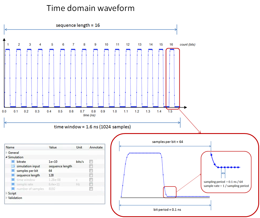
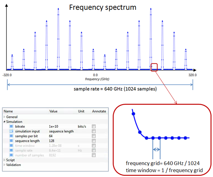
Where Ts is the sampling period. For instance, for a bit rate of 10 GBits/s, 16 bits and 64 samples per bit, the number of samples is 1024, the time window is 1.6 ns, and the sample rate is 640 GHz. The time domain waveform will have the following properties:
The frequency domain information is:
Depending on the simulation input property, these parameters can be calculated automatically by INTERCONNECT.