This section describes how to rescale far field projections to distances other than the default of 1m. It also describes how to use the farfieldexact functions to calculate the field distribution at arbitrary positions, including the so called intermediate field (beyond the simulation region boundary, but not yet the far field).
Note: The descriptions and examples of the far field projection calculation on the following pages are primarily intended for users of FDTD. For users interested in calculating far field projections with MODE, these descriptions are basically still correct, although some subtle differences do exist.
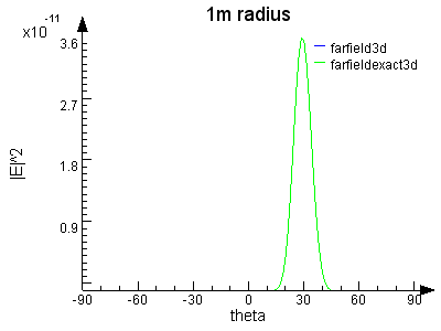
The script file first calculates the standard far field distribution. Rather than calculating the distribution on the entire hemisphere, we only get one line at y=0. This data is calculated with both the farfield3d and farfieldexact3d functions. As the following figure shows, both functions return the same result for the field distribution on a hemisphere with a radius of 1m.
In most cases, the standard projection location is sufficient. However, if you wish to know the field amplitude at a different distance (such as a hemisphere with a radius of 1mm), we recognize that the E and |E|^2 scale as shown in the following table. This formula is valid anywhere in the far field.
|
Electric field scaling |
Electric field intensity scaling |
|
||
|
2D |
$$\overrightarrow{E}(R)=\overrightarrow{E_0}/\sqrt{R}$$ |
$$\mid\overrightarrow{E}(r)\mid^2=\frac{\mid\overrightarrow{E}(1)\mid^2}{r}$$ |
|
|
|
|
3D |
$$\overrightarrow{E}(R)=\overrightarrow{E_0}/R$$ |
$$\mid\overrightarrow{E}(r)\mid^2=\frac{\mid\overrightarrow{E}(1)\mid^2}{r^2}$$ |
|
Projections to the intermediate field
If you want to calculate the field distribution quite close to the structures (the intermediate field), then the farfieldexact functions must be used. The intermediate field is the region close to the structure where the fields are not yet propagating like simple plane waves. The farfieldexact functions are able to calculate the field distribution in the far field or intermediate field (to within a few wavelengths of the simulation region).
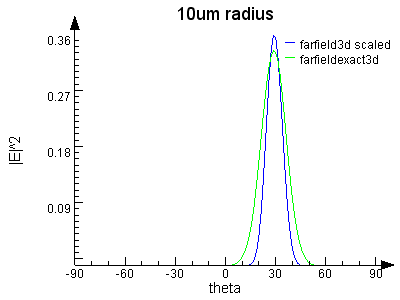
For example, suppose we wish to know the fields on an a hemisphere with a radius of 10um. One approach (blue line in following figure) might be to simply scale the fields by a factor of (1m/10um)^2. This is NOT correct because 10um is not far enough to be considered as the far field. The EM fields are not yet propagating like simple plane waves. The correct approach is to use the farfieldexact3d function (green line).

As you can see, the two calculations do not give the same results. The blue line is not quite correct because rescaling the far field distribution is not correct in the intermediate field.
|
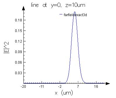
Note: Projections to surfaces other than hemispheres Use the farfieldexact functions when you want the field distribution on a surface other than a hemisphere. The following figure shows the field intensity along a straight line for x=-20:20um at y=0um, z=10um.
|