Introduction
Many photonic circuits incorporate Fabry-Perot cavities and ring resonators, to produce peaks that are periodic as a function of frequency. The spacing in frequency between adjacent peaks is called the Free Spectral Range (FSR) and may, itself, also vary as a function of frequency. The FSR is an important quantity in the design of these circuits, and therefore, its accurate calculation is highly desirable. The FSR is inversely related to the round-trip group delay in a Fabry-Perot cavity or the group delay in making a loop around a ring resonator structure. When the round trip optical path length is such that this group delay is not an integer multiple of the simulation sample period, the modeled group delay deviates from its actual value, and lowers the accuracy of the FSR value in the simulated spectra. The deviation will decrease with increasing sample rate, however, increasing the sampling rate leads to longer simulation times for a given desired spectral resolution. It is possible however, to accurately model the group delay near the centre of the simulation bandwidth using the fractional delay option in the waveguide elements in INTERCONNECT, thereby greatly increasing the accuracy of the FSR's in the simulated spectra.
In this example, the fractional delay option is employed to accurately calculate and measure the FSR of a Fabry-Perot cavity without resorting to large sampling rates.
Simulation
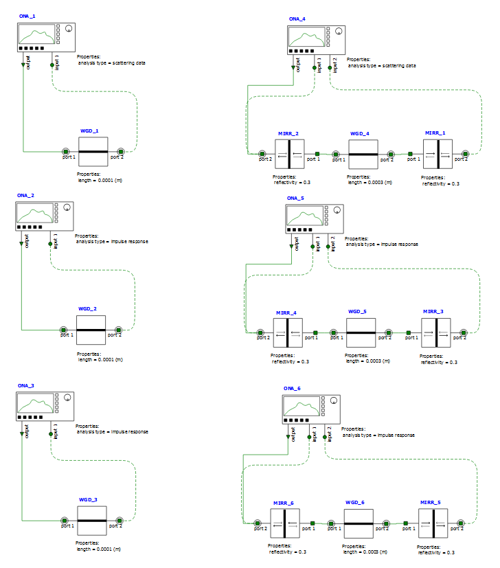
The INTERCONNECT project file fractional_delay.icp contains six circuits as shown in Figure 1. The first three are comprised of an Optical Network Analyzer (ONA) and optical waveguide. Referring to Figure 1, a highly spectrally sampled frequency-domain simulation is performed by the ONA_1/WGD_1 circuit and the group delay is measured by ONA_1. The ONA_2/WGD_2 and ONA_3/WGD_3 perform similar calculations of group delay in the time-domain with the fractional delay option on their respective waveguides set to false and true, respectively.
The last three circuits are each comprised of an ONA connected to a Fabry-Perot cavity modeled using a pair of mirrors linked by waveguides. Referring, again, to Figure 1, a highly spectrally sampled frequency-domain simulation is performed by the ONA_4/MIRR_1/WGD_4/MIRR_2 circuit and the FSR spectrum measured by ONA_4. The ONA_5/MIRR_3/WGD_5/MIRR_4 and ONA_6/MIRR_5/WGD_3/MIRR_6 perform similar calculations of the FSR in the time-domain with the fractional delay option on their respective waveguides set to false and true, respectively.
Instructions
- Open INTERCONNECT, load the file fractional_delay.icp, and run the simulation
- Load and run the script, fractional_delay_plotResults.lsf.
Results and Discussion
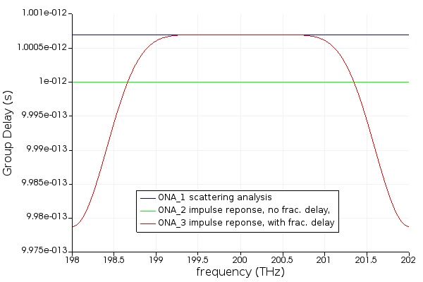
Figure 2 depicts the group delays in each circuit measured as calculated by their respective ONA's based on the complex transmission produced by simulation of the propagation through the waveguides.
As can be seen from the figure, the FSR from the circuit with fractional delay enabled on the waveguide produced much better agreement with the reference, i.e., the highly-spectrally sampled frequency domain (scattering analysis), over the central portion of the simulation, than the circuit with fractional delay disabled. However, it is also evident that near the edges of the simulation band, enabling fractional delay causes a greater deviation from the reference than disabling it.
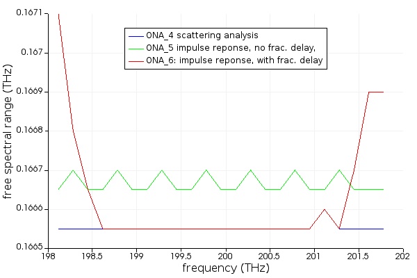
Figure 3 depicts the FSR's in each circuit as calculated by their respective ONA based on the reflectivity spectra produced by the simulation. Here again, the FSR from the circuit with fractional delay enabled on the waveguide produced much better agreement with the reference over the central portion of the simulation than the circuit with fractional delay disabled. And, as in Figure 2, near the edges of the simulation bandwidth the agreement with the reference is diminished by enabling fractional delay. The results are thus consistent with the notion that the inaccuracy of the FSR results arise from the difficulty in accurately modeling delays through arbitrary lengths of waveguide at finite sampling frequencies.
It should be emphasized that all of the time domain (impulse response) simulations were carried out at the same sample rate. Therefore, it is possible to increase the accuracy of group delay and FSR calculations at and near the center frequency by enabling the fractional delay option on the waveguide elements in INTERCONNECT, albeit at the cost of less accuracy nearer to the simulation band edges of the simulation bandwidth.