This page provides more information on the Advanced Options part of the Eigensolver analysis window.
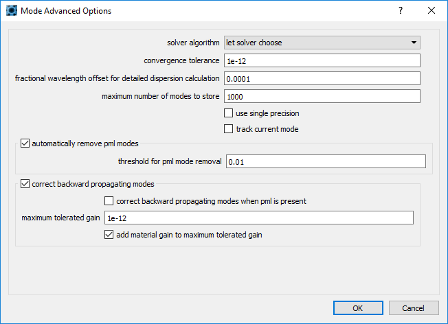
- SOLVER ALGORITHM: The default option is 'let solver choose'.
- E transverse: It solves for the electric field components tangential to the FDE region. This was the default option for the legacy versions of the products.
- H transverse: It solves for the magnetic field components tangential to the FDE region.
- E and H: It solves for all field components, which is necessary for anisotropic waveguide calculations.Note that it will require three times more memory than the above two options.
- Let solver choose: The FDE solver will try to pick the most suitable option (default value).
- CONVERGENCE TOLERANCE: The convergence tolerance used for the calculations - the default value corresponds to 1e-12 but can be increased by the user to speed convergence or decreased to improve accuracy.
- FRACTIONAL OFFSET FOR DETAILED DISPERSION CALCULATIONS: this is the fractional frequency offset used for calculating numerical derivatives with respect to frequency, when the "detailed dispersion" checkbox is on.
- MAXIMUM NUMBER OF MODES TO STORE: When searching for modes from n1 to n2, the algorithm will stop when this many modes have been found.
- USE SINGLE PRECISION: Some parts of the core calculations performed by MODE can be done in single precision. This can save some memory and time, but also decreases the accuracy of the results.
- TRACK CURRENT MODE: When tracking multiple modes, the search index can follow the first mode in the list or the current mode. The current mode is typically the last mode selected and is the mode that is currently plotted. If the effective indices of the modes are sufficiently different, some modes may be lost. In general, this can be fixed by increasing the number of trial modes.
- AUTOMATICALLY REMOVE PML MODES: When this is checked, un-physical modes that have their energy primarily in the PML are removed and discarded.
- THRESHOLD FOR PML MODE REMOVAL: When PML mode removal is on, modes are discarded if the fraction of magnetic field intensity in the PML is larger than this threshold.
- CORRECT BACKWARD PROPAGATING MODES: When this is checked all modes will have imag(neff) ≥ -gain_max , however some modes may have negative real(neff) correspondent to a negative phase velocity. The value of gain_max should be zero when the waveguide is made from materials with no gain, however, we typically use a finite value for two reasons: firstly, there can be small numerical errors such that a mode with imag(neff) = 0 may be calculated to have a numerically small, negative value such as -1e-15, and secondly, the waveguide itself may be composed of some materials that, intentionally, have gain – in other words they have imag(n) < 0 where n is the material refractive index. The value of gain_max is given by gain_max = “maximum tolerated gain” + material_gain_max, where “maximum tolerated gain” is specified below and material_gain_max is the maximum value of |imag(n)| for any material in the waveguide that has gain. If no material in the waveguide has gain, then material_gain_max = 0.
- CORRECT BACKWARD PROPAGATING MODES WHEN PML IS PRESENT: By default, the detection and correction of backward propagating modes, as described above, is not performed when any of the FDE solver boundaries are PML. When PML boundaries are used, you must check this box to apply the correction of backward propagating modes. However, we do not generally recommend checking this box because PML itself can create small amounts of gain in some modes which is typically an indication that the PML is too close to the guiding structure and not that the backward propagating mode has been accidentally selected. In addition, evanescent modes with negative phase velocities are rarely found when PML is used.
- MAXIMUM TOLERATED GAIN: This quantity is used to calculate gain_max, as described above. Since this is typically used for avoiding accidental sign reversal due to small numerical errors, this value is typically very small and the default is 1e-12.
- ADD MATERIAL GAIN TO MAXIMUM TOLERATED GAIN: When this is checked, the material gain (if any gain materials are present) will be included in the calculation of gain_max, as described above. When this is unchecked, gain_max will be equal to “maximum tolerated gain”.
For more information such as tips on finding a mode and lossy mode, please see Working with lossy modes and dB/m to k conversion.