This section describes the far field spatial filtering option.
| Note: The descriptions and examples of the far field projection calculation on the following pages are primarily intended for users of FDTD. For users interested in calculating far field projections with MODE, these descriptions are basically still correct, although some subtle differences do exist. |
For far field projections to be accurate, all radiation that will propagate to the far field must pass through the monitor being used for the projection. The far field projection functions assume that the EM fields are zero beyond the edge of the monitor. This effectively truncates the near fields at the monitor edge.
In some cases, the monitor (and simulation region) would have to be impractically large to ensure that all of the radiation passes through the monitor. One such simulation is the angular distribution of a dipole near an interface. To reproduce these results, run the simulation file and then the script.
The blue line in the following figure shows the near field data just above the interface surface. The far field projection functions will use this data to calculate the far field intensity. The important point to notice is that the near field data is non-zero near the edge of the plot (red circles). It is obvious that the these near fields do not immediately go to zero at x=8um, but that is what the far field projections assume.
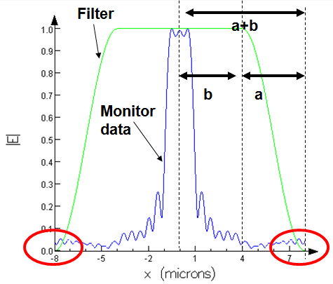
This truncation will lead to high frequency ripple in the far field projection data. The far field filter option allows us to apply a spatial filter to the near field data (shown in green). When the fields go more smoothly to zero, the high frequency ripple is removed from the projection. Both projections are shown below. Change the far field filter setting in the script file to reproduce each of these results.
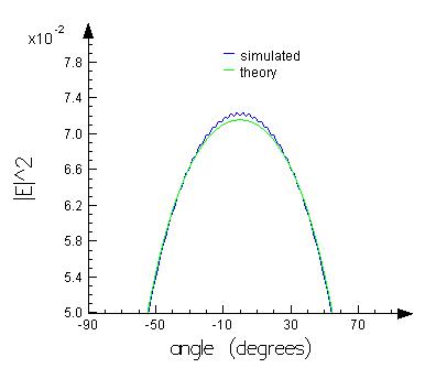
farfieldfilter(0); |
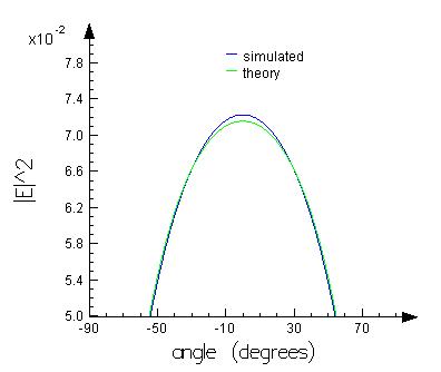
farfieldfilter(1); |
It is important to realize that the far field filter does not make the projection more accurate. The filter simply removes high frequency ripple caused by the field truncation. To increase the accuracy, the monitor (and simulation region) must be made wider, so the monitor can record more of the fields that will eventually propagate to the far field.
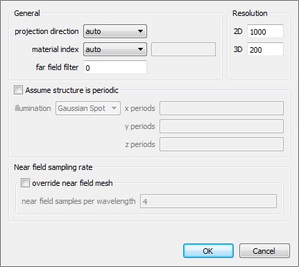
The far field filter has a single input parameter, which is a number between 0 and 1. By default, it is 0, which turns the filter off. This filter is applied to all far field projections. The filter parameter defines the width of the filter by the following formula: α = (a)/(a+b).
|
Note: Periodic structures - far field filter The far field filter option should not be used for periodic structures. Set it to zero when using the 'assume periodic' option. |