This section describes how to get the locations of the mesh points.
Measure the mesh with the ruler
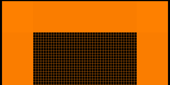
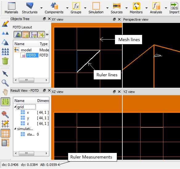
The mesh can be viewed in the CAD layout editor by clicking the View simulation mesh button. The simulation mesh is not constantly updated as simulation objects are manipulated because it would make the interface too slow. The Recalculate simulation mesh (F5) button can be used to force a recalculation of the mesh.
Once the mesh is visible, the Ruler (R) mouse mode can be used to measure the mesh size. The ruler measurements are visible at the bottom of the screen.
When viewing the mesh (orange), it is often best to hide the drawing grid mesh (grey) to keep the screen from becoming too cluttered. To hide the drawing grid, click on the Edit drawing grid button, and unselect "Show grid".
Getting the mesh from Simulation region properties
Before a simulation has been run, some information about the mesh can be obtained by getting the Simulation region properties.
addfdtd;
?getresult("FDTD","x"); # it will return the x positions of the grid points

result:
-8.5e-007
-8.10465e-007
-7.7093e-007
-7.31395e-007
-6.9186e-007
-6.52326e-007
-6.12791e-007
-5.73256e-007
-5.33721e-007
-4.94186e-007
...
...
...
Getting the mesh from monitor data
After a FDTD or propagator simulation has been run, the mesh point locations can be easily obtained from the monitor data. Generally, monitors record data at each mesh point. The getdata command can be used to get the x,y,z position vectors of the monitor data. These vectors will specify the position of each mesh point that intersect the monitor. To obtain the mesh point positions in the X,Y plane, use a 2D monitor located in the XY plane. The following script commands will get the x position vector from monitor1.
m="monitor1";  # monitor name
x=getdata(m,"x");  # x position data