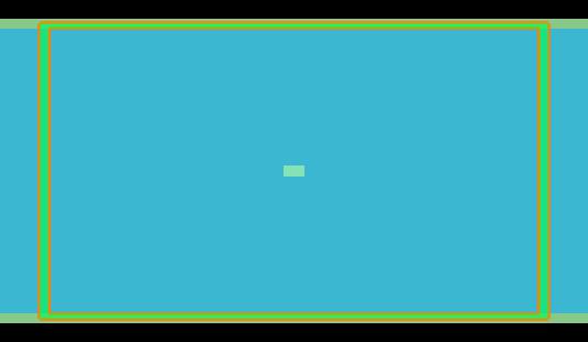
A stripline is formed by a conducting strip in a substrate sandwiched by ground planes above and below the strip. The characteristic impedance of a mode supported by a stripline can be calculated using the built-in “Power and impedance integration” tool in MODE FDE solver. In this example, we consider a device with an inner strip of perfect electrical conductor with a finite thickness, as well as a 2D strip which can be more easily compared with analytic results where the strip is assumed to have zero thickness.
Background
The characteristic impedance is calculated in the FDE solver by using a surface integral to calculate the power carried by the mode, and loop integral to calculate the current flow through the loop.
$$P=\int_{S} P \cdot d S$$
$$I=\oint_{c} H \cdot d \lambda$$
Then the characteristic impedance is calculated using
$$Z 0=\frac{P}{I^{2}}$$
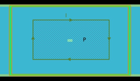
An example integration path and area for the loop and surface integrals are illustrated below.

This calculation method requires the user to specify the integration region. You can specify the integration region before you run the simulation from the FDE solver’s “Impedance calculation” tab.

Or, the FDE solver also includes a built-in “Power and impedance integration” tool which allows you to specify the integration region after solving for the modes and selecting the desired mode from the mode list. When the integration quantity is set to “current”, the tool will calculate the characteristic impedance using the specified integration region.
Simulation Setup
Comparing with analytic results
We can verify the calculated characteristic impedance returned using the “Power and impedance integration” tool by comparing it against the characteristic impedance of an infinitely thin conductor calculated from equation 3.179 from the text by Pozar [1].
Run the stripline_Z0.lsf script file which prints out expected characteristic impedance of approximately 51.63 ohms for the given strip width, relative permittivity of the substrate, and substrate thickness. Note that the equation from Pozar which is used is not an exact solution, but it is quoted as being accurate to about 1% of the exact results.
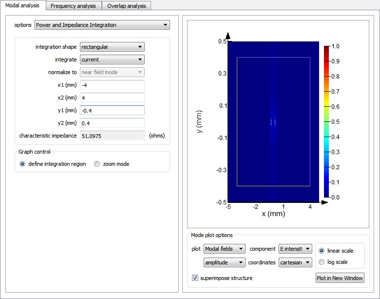
Next, run the stripline_2D.lms file. After calculating the modes, select the first mode in the mode list, and from the “options” drop down menu select “Power and Impedance Integration”. Then under the “integrate” drop down menu, select “current” to perform the characteristic impedance calculation. You can specify the integration region by setting the x1, x2, y1, and y2 parameters, or you can also use your mouse to click and drag on the plot on the right-hand side to select the integration region from the plot.

The size of the integration region should be set so that it fully encloses the central strip which carries the current. The calculated characteristic impedance returned by the tool is approximately 51.1 ohms. You can get an even more accurate result by using a finer mesh over the structure, and this particular structure can require a relatively fine mesh to get an accurate field profile because the fields are strongly concentrated at the points on the left and right edges of the strip.
3D strip with finite thickness
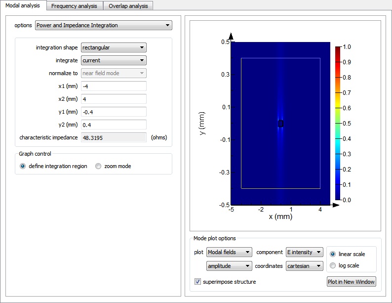
Run the stripline_3D.lms file. Using the same method as before, you can calculate the characteristic impedance of about 48.5 ohms for the 3D strip with thickness of 35 microns. To get the results to be closer than the one from Pozar and stripline_2D.lms, you can reduce the thickness of the strip and use a finer mesh. In general, it is more efficient to use 2D geometries to represent very sub-wavelength layers like in this example.

Related references
[1] D.M. Pozar, Microwave Engineering, Fourth Edition. John Wiley & Sons (2012).